GEOMETRY CHECKS
Aircraft Symmetry and Incidence Checks
General preparation and measurement principles for aircraft symmetry and incidence checks.
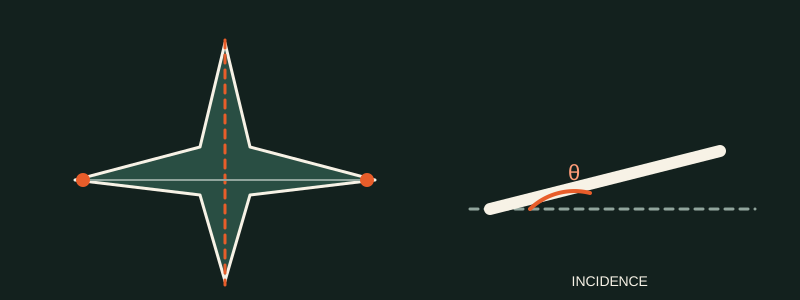
Key reference points
- Use aircraft-specific datum points and configurations.
- Control environmental and loading conditions.
- Repeat abnormal measurements before evaluation.
Organised training notes
1Prepare and level
Establish the aircraft configuration and level attitude required by the applicable procedure.
- 1.1 EnvironmentUse the required surface or hangar condition and control wind, sunlight and temperature effects.
- 1.2 Loading and locksSet fuel, doors, controls, ground locks and other configuration items exactly as specified.
2Measure the defined geometry
Use calibrated equipment at the aircraft-specific datum, symmetry stations and incidence lines.
- 2.1 SymmetryCompare corresponding left and right reference-point distances using the specified tension and alignment method.
- 2.2 IncidenceMeasure the wing or stabilizer angle against the approved reference plane with the specified fixture or inclinometer.
- 2.3 Related alignmentDihedral, twist, fin verticality, toe and camber are separate checks and must retain their own approved setup.
3Verify and evaluate
Record results consistently and repeat abnormal measurements before drawing structural conclusions.
- 3.1 Repeat the setupRecheck level, reference points, equipment position and reading method when a result exceeds its limit.
- 3.2 Use the stated comparisonCalculate only the difference or angle required by the approved procedure.
Training-reference boundary
This summary is not approved repair or maintenance data. Do not inspect, classify, select material, alter structure or perform a repair from this page alone. Use the current applicable SRM, AMM, engineering order, drawing and company procedures.