CONTROL SURFACE BALANCE
Control-Surface Static Balance
General static-balance concepts for repaired or repainted aircraft control surfaces.
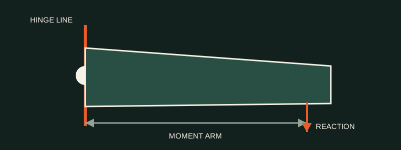
Key reference points
- Repair and repaint can change hinge-line moment.
- Balance categories and limits are aircraft-specific.
- Record the rework and accepted final balance result.
Organised training notes
1Understand the moment change
Static balance relates a weight reaction to its perpendicular arm from the defined hinge centreline.
- 1.1 Balance momentUse the approved sign convention and measurement points for the specific surface.
- 1.2 Rework momentMaterial removed or added during repair or repaint changes the moment according to weight change and location.
2Use the correct setup and limit
The included parts, fixture, attitude, reaction point, scale and limit must match the control-surface category.
- 2.1 Measurement setupUse the specified hinge fixture or approved on-aircraft calculation method and calibrated equipment.
- 2.2 Balance limitsManufacturing, operational and rework limits serve different purposes and must not be interchanged.
3Record the accepted result
Maintain the control-surface rework and balance history required by the approved data.
- 3.1 Rework recordRecord repairs, paint changes, weight changes, locations, method and final result.
- 3.2 Release boundaryIf the surface cannot meet its applicable limit, follow the approved replacement or engineering route.
Training-reference boundary
This summary is not approved repair or maintenance data. Do not inspect, classify, select material, alter structure or perform a repair from this page alone. Use the current applicable SRM, AMM, engineering order, drawing and company procedures.