MECHANICAL FLIGHT CONTROLS
Control Cables, Routing Hardware and Rigging Checks
General construction, routing and rigging principles for aircraft mechanical control cables.
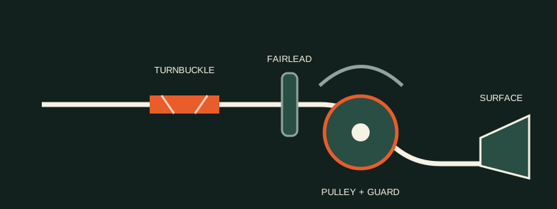
Key reference points
- Treat the cable system as one complete load path.
- Use pulleys, fairleads and terminals only for their approved purpose.
- Verify tension, travel, direction and security with approved data.
Organised training notes
1Cable and terminal construction
Confirm cable construction, diameter, material and terminal type from the approved system data.
- 1.1 Cable constructionStrand designations such as 7 × 7 and 7 × 19 describe construction, not permission to substitute one cable for another.
- 1.2 TerminalsSwaged, thimble-eye and other terminal systems have different tooling, strength and inspection requirements.
- 1.3 Swage inspectionCheck the approved diameter or gauge result, surface condition, cable position, slippage and broken wires.
2Routing hardware
Inspect each routing component for condition, alignment, security and correct purpose.
- 2.1 Pulleys and guardsPulleys change cable direction; guards retain the cable without interfering with pulley rotation.
- 2.2 Fairleads and pressure sealsFairleads guide and protect a substantially straight run; pressure seals preserve the pressure boundary where specified.
- 2.3 Turnbuckles and linksTurnbuckles adjust tension and require the approved thread engagement, locking and safetying method.
3Inspection and rigging
Set the system using the aircraft-defined neutral position, cable-tension correction and travel limits.
- 3.1 Cable conditionInspect for external and internal wear, broken wires, corrosion, distortion and damage near pulleys, fairleads and terminals.
- 3.2 Tension and travelUse calibrated equipment, the correct cable-size chart and the applicable temperature-correction data.
- 3.3 Final operationVerify cockpit-to-surface direction, synchronization, freedom of movement, stops, security and independent inspection.
Training-reference boundary
This summary is not approved repair or maintenance data. Do not inspect, classify, select material, alter structure or perform a repair from this page alone. Use the current applicable SRM, AMM, engineering order, drawing and company procedures.